What laser values are published for VIM30CF?
The model is listed at 30W with a 10.6 μm wavelength. It is the lowest-power entry in the VIM-CF flying CO2 family, whose next entry is VIM40CF at 40W.

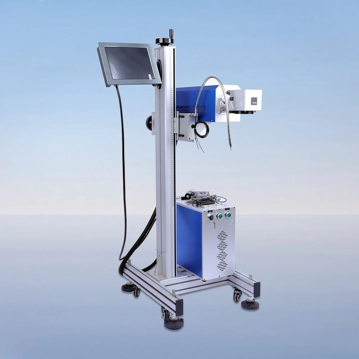
Laser Marking Machine
VIM30CF is the 30W model in the VIM-CF flying CO2 laser marking series. Its published wavelength is 10.6 μm. The flying design is described for marking moving materials or workpieces, so the intended product movement and the marking position are part of the configuration discussion from the beginning.
This is the lowest power listed in the VIM-CF family, followed by 40W, 60W, 100W and 150W models. Its power entry does not establish a particular line speed. The actual graphic, substrate and required placement need to be presented together with the proposed line arrangement.
| Specification | VIM30CF |
|---|---|
| Laser Power | 30W |
| Laser Wavelength | 10.6 μm |
Configuration options vary by model. Confirm the final specification, selected components and operating requirements with your quotation.
The series configuration includes a CO2 tube, air cooling, a galvo scanner and a field lens. A red dot pointer provides visible positioning. Ask for the proposed arrangement of those components at the intended marking point, using a layout that shows the product's orientation as it passes the equipment.
The control system supports parameter settings, adjustment and real-time monitoring. Describe the required mark and whether its content changes between jobs. A review using that information can establish the proposed control arrangement without presuming that a particular software package or production-line interface is included.
The adjacent VIM40CF model is listed at 40W, while VIM30CF is 30W. Compare them around one consistent task. Keep the required graphic size, product spacing and substrate information unchanged so that a power comparison does not become confused with a change in the proposed application.
The CO2 tube configuration names wood, acrylic and glass for marking and engraving. Identify the actual material and surface finish for the moving workpiece. The published scope does not provide a tested result on every grade or coating, so the required appearance and any relevant inspection criteria should accompany the task description.
Draw the direction of movement and the desired mark position on the product. Include spacing between items and the access available around the marking point. The flying design describes the marking arrangement; it does not establish a supplied conveyor, an unrestricted integration capability or an unattended production line.
Request the marking field, lens and control configuration proposed for VIM30CF. No field dimensions, minimum character size or software brand are assigned on this page. Keep the selected equipment details alongside the 30W model so the proposal can be checked against the artwork and line layout.
Air cooling and an interlock are described. The interlock stops operation when a safety door or panel opens. Obtain the operating instructions and actual protective arrangement for the proposed installation; the component description does not certify the completed line or establish a continuous operating duration.
Separate the equipment already present on the line from items requested with the marker. State which dimensions and product movements are fixed, and identify where the controls must be accessed. This defines a useful VIM30CF enquiry around the selected power, marking task and installation boundary rather than an assumed package of handling equipment.
The model is listed at 30W with a 10.6 μm wavelength. It is the lowest-power entry in the VIM-CF flying CO2 family, whose next entry is VIM40CF at 40W.
It describes marking moving material or workpieces. No line-speed value or supplied conveyor is established by that description, so the actual product movement and equipment scope need to be defined.
Wood, acrylic and glass are named for marking and engraving in the CO2 tube configuration. Provide the precise substrate and surface information for the intended VIM30CF task.
Show the desired location on the product, its orientation, direction of travel and spacing. Include the artwork dimensions and available access around the proposed marking point.
Confirm the 30W model, marking field, optics and controls, together with the installation arrangement. Identify any requested handling accessories separately rather than assuming they accompany the marker.
Share your material, dimensions and process. Start a conversation about the right configuration.