What are the listed VIM30CS power and wavelength?
VIM30CS is listed at 30W and 10.6 μm. It is the lowest power entry in the VIM-CS split CO2 family, with VIM40CS providing the next published 40W choice.

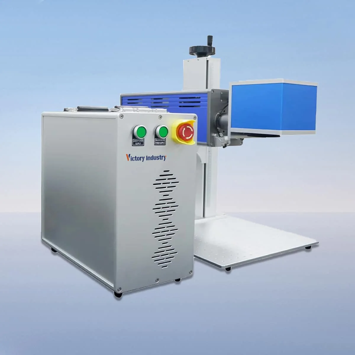
Laser Marking Machine
VIM30CS is the 30W model in the split-design VIM-CS CO2 laser marking series, with a published wavelength of 10.6 μm. It is the first power entry in the family, followed by VIM40CS, VIM60CS, VIM100CS and VIM150CS at their respective listed powers.
The split arrangement separates the laser source or marking unit from the control unit. For the 30W model, that makes the proposed equipment layout a useful starting point for an enquiry. Identify the workpiece location and the preferred control position, then request the actual connections and placement requirements for the supplied arrangement.
| Specification | VIM30CS |
|---|---|
| Laser Power | 30W |
| Laser Wavelength | 10.6 μm |
Configuration options vary by model. Confirm the final specification, selected components and operating requirements with your quotation.
The configuration describes a CO2 tube with air cooling, a galvo scanner and a field lens. A red dot pointer provides a visible reference for positioning the marking area. These named components should appear in the proposal, together with the specific optical arrangement selected for the graphic you intend to use.
Settings, adjustments and real-time monitoring are described for the control system. When planning the work position, show where the operator will view the part and use those controls. Provide an example of the artwork and explain what changes between jobs so the proposed operating arrangement can be discussed concretely.
VIM30CS and VIM40CS share the series' split layout but have different listed powers: 30W and 40W. Keep the same part and appearance requirements when comparing them. Neither the layout nor the power entry establishes a marking time, a character-size limit or a guaranteed result on a particular surface.
The product description names plastics, glass and ceramics as intended marking and engraving materials. Identify the actual material and its finish for a VIM30CS enquiry. Include the area to be marked and the appearance you need, particularly where different coatings or surface conditions are involved in the same purchasing brief.
A split machine layout needs to be considered together with the workpiece support. Supply a drawing showing the part, the marking face and available access. The separation of units does not establish an allowable part weight or an unlimited workpiece size; dimensions and holding arrangements still need to be discussed for the intended task.
Request the selected lens and working field with the VIM30CS offer. No numerical field size is assigned here, and the visible pointer does not supply that dimension. Attach the graphic at its intended size and show its location on the part so the optical proposal and the layout can be reviewed together.
The described interlock stops the machine when a safety door or panel opens. Obtain the operating instructions and clarify the protective provisions for the actual setup. Air cooling is also listed, but the source description does not assign a continuous operating schedule or a safety class for the complete installation.
Keep the marker, controls and requested accessories identifiable in the purchasing scope. Ask for actual unit dimensions, connecting arrangements and installation requirements before finalizing a workstation layout. Split construction does not specify a connection length, so the preferred distance between the equipment and controls must be checked rather than assumed.
VIM30CS is listed at 30W and 10.6 μm. It is the lowest power entry in the VIM-CS split CO2 family, with VIM40CS providing the next published 40W choice.
The source describes the laser source or marking unit separately from the control unit. It does not supply a connection length, so confirm the proposed arrangement against your workstation layout.
Plastics, glass and ceramics are named as intended marking and engraving materials. The actual grade, finish and required appearance should accompany the enquiry; no individual part result is established here.
No numerical workpiece size or weight capacity is assigned. Provide the part dimensions, support and access requirements to discuss the actual proposed marking arrangement.
Show the graphic dimensions and position on the part, plus any details that change between jobs. Request the lens, working field and offered control arrangement using that information as a reference.
Share your material, dimensions and process. Start a conversation about the right configuration.