How do VIM30CD and VIM40CD differ?
Their listed powers are 30W and 40W respectively. Both are VIM-CD desktop CO2 models with a published wavelength of 10.6 μm; the task still needs its own configuration review.

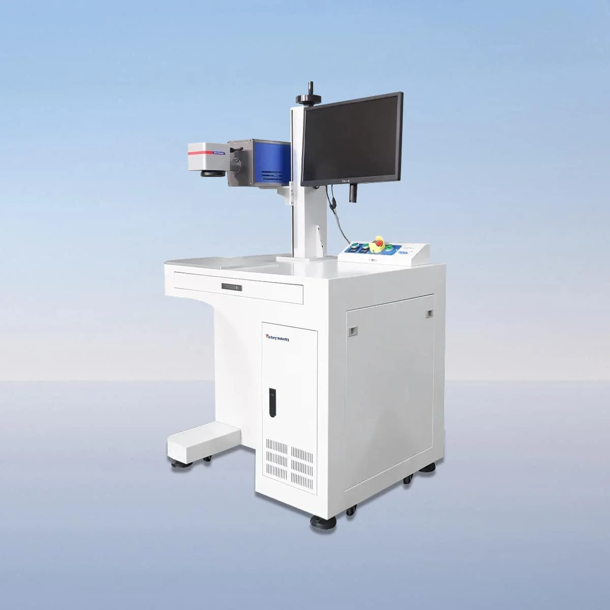
Laser Marking Machine
VIM-CD is a desktop CO2 laser marking machine series with five power choices. VIM30CD is listed at 30W and VIM40CD at 40W; VIM60CD, VIM100CD and VIM150CD extend the range to 60W, 100W and 150W. All five share the published 10.6 μm wavelength. The desktop arrangement is the series' physical starting point for workstation planning.
The configuration brings together a CO2 laser tube, air cooling, a galvo scanner, a field lens and a red dot pointer. The control system provides parameter setting, adjustment and real-time monitoring. These are equipment features to review alongside the intended mark, material and handling arrangement rather than a ready-made process for every workpiece.
Choose an individual model below to view its complete technical specification. The series overview shows selected parameters for comparison.
VIM30CD and VIM40CD differ in their listed laser power. Moving through the other models changes that power selection, while the wavelength remains the same. Choose the model with the proposed marking task in view; a higher power entry alone does not specify the contrast, depth or cycle time of a particular design.
A red dot pointer provides a visible reference for positioning. This is useful to include in a setup demonstration using the intended workpiece outline and mark location. The galvo scanner and field lens are separately identified optical components, so the proposed optical arrangement should be included when the machine configuration is confirmed.
Air cooling is part of the listed equipment. An interlock is also described that stops operation when a safety door or panel opens. Review the actual loading arrangement and operating instructions for the proposed desktop installation. The presence of those components does not define a continuous operating duration or a certified safety classification.
The published application scope covers marking and engraving on nonmetal materials including wood, acrylic, glass and plastic. Describe the exact substrate and any coating rather than using only a broad material name. The required appearance belongs beside the artwork: specify the intended size, position and any detail that must remain legible on the finished item.
For a desktop station, show how the part will rest and how its marking surface will be presented. Include the overall object dimensions even when the mark itself is small. If several parts share the station, provide their different outlines and reference edges so the setup discussion covers positioning as well as the graphic content.
The five-model table identifies power and wavelength, while the proposed machine needs an optical and control configuration appropriate to your work. Ask for the marking field and software details to be specified in that proposal. This avoids borrowing an area or software name from a different marking series with a similar appearance.
Prepare the artwork at its intended size and identify which elements stay fixed and which will change between jobs. A drawing of the mark location can be kept beside that file. During the control review, establish how the team will enter settings, adjust the job and monitor operation, using the offered system rather than an assumed interface.
Finally, plan the physical station with actual equipment dimensions. Allow for loading, access to the controls and the workpiece support arrangement required for the job. The desktop description does not provide a machine weight or a suitable bench specification; those details belong in the installation information for the selected configuration.
Their listed powers are 30W and 40W respectively. Both are VIM-CD desktop CO2 models with a published wavelength of 10.6 μm; the task still needs its own configuration review.
The remaining entries are VIM60CD at 60W, VIM100CD at 100W and VIM150CD at 150W. Identify the full model in the equipment request to keep the power choice explicit.
The source describes marking and engraving on wood, acrylic, glass and plastic. This is an application scope, not a tested result for every grade, coating or finished-part requirement.
The configuration includes a red dot pointer for visible positioning. Provide the part outline and desired mark location when reviewing the setup and the workpiece support arrangement.
No marking-area value is assigned on this page. Request the proposed field, optics and control details together with the selected power and the artwork to be processed.
Share your material, dimensions and process. Start a conversation about the right configuration.