How do VIC6040D and VIC9060D differ?
VIC6040D is listed at 600*400mm and VIC9060D at 900*600mm. Both share the published 80-600W laser power range and the dual-head series description.

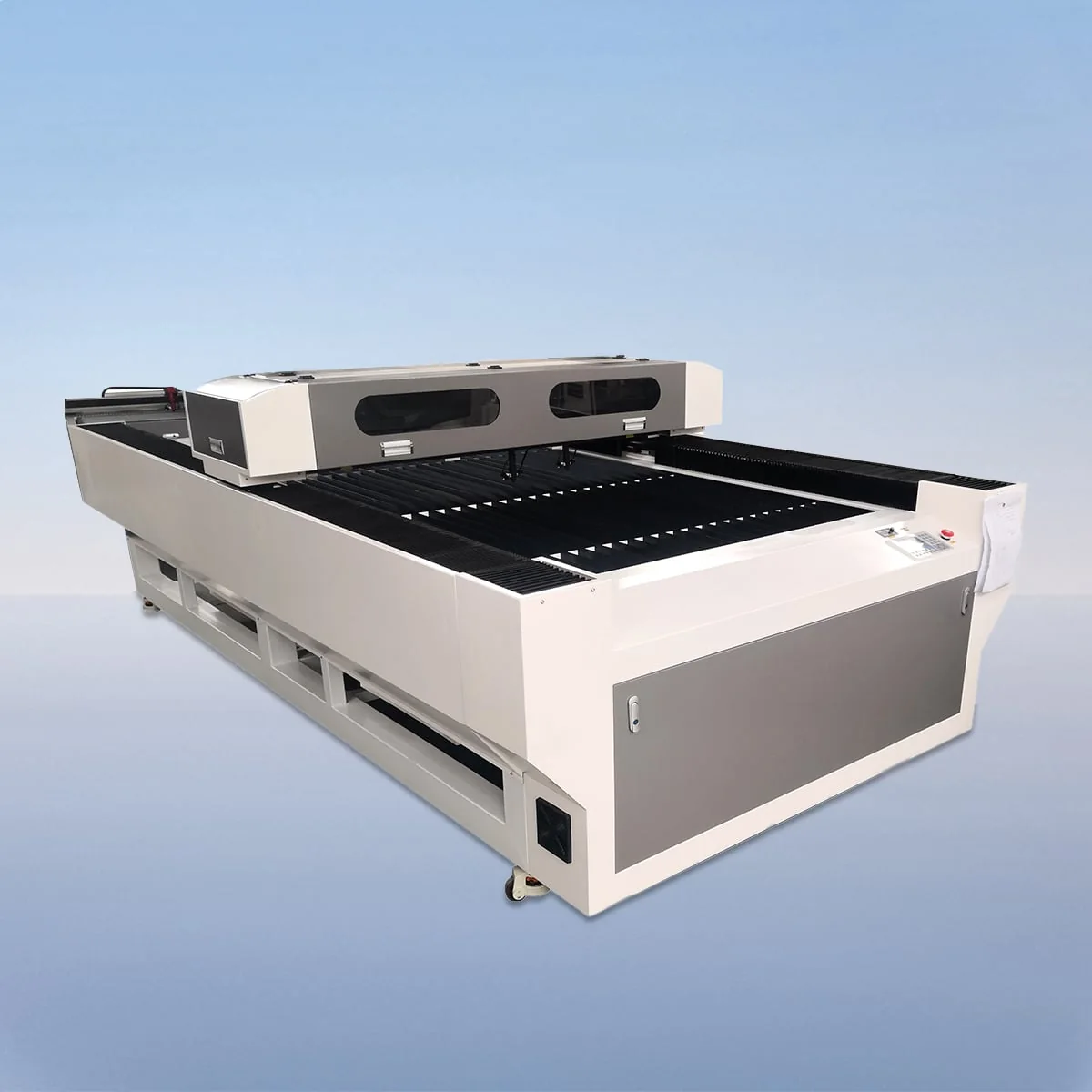
Laser Cutting Machine
VIC-D is a dual-head CO2 laser cutting machine series for the non-metal cutting uses described on its product page. Two cutting heads work simultaneously. A CO2 tube, linear guides, stepper motor and belt drive complete the main structure described for the family.
Its seven working-area models run from VIC6040D to VIC1530D, with a common 80-600W laser power range. Acrylic, wood, paper and rubber are the named material examples. A purchase discussion should connect the chosen format with a specific part layout, material and thickness.
Choose an individual model below to view its complete technical specification. The series overview shows selected parameters for comparison.
VIC6040D provides a 600*400mm working area and VIC9060D provides 900*600mm. These are the two smallest formats listed. For a larger outline, VIC1390D offers 1300*900mm and VIC1610D offers 1600*1000mm. Each pair of dimensions describes the machine working area once, even though the series has two heads.
The longer formats are VIC1318D at 1300*1800mm, VIC1325D at 1300*2500mm and VIC1530D at 1500*3000mm. The final choice needs the intended arrangement of the parts, not just the dimensions of one isolated shape. Show the whole layout you want to discuss.
A red dot pointer is optional. It projects a visible point onto the workpiece for positioning. The described aluminum blade worktable sits alongside the table specification of Knife Table or Honeycomb Table, so the surface and requested pointer should be named as configuration choices.
For VIC-D CO2 laser cutting machine planning, include an individual part drawing and a layout drawing. Use the individual view to identify the material, thickness and required features. Use the layout to show repetitions, orientation and the relationship between shapes. The two views answer different questions about the proposed task.
Keep cutting instructions clear where the design contains more than one operation. If several part types are involved, label them and give their quantities separately. A combined order total can conceal whether the work consists of many identical pieces or a mixture of designs.
The dual-head description establishes simultaneous operation; it gives no head spacing or numerical output increase. Those limits leave a practical question for the configuration discussion: how should the proposed layouts be arranged for this equipment? Providing the actual files is more useful than calculating twice the output from the number of heads.
Ruida with USB interface is the listed control. PLT, DXF, BMP, JPG and AI are included in the graphic-format list. Identify the format of each submitted file and keep the drawing revision with its instructions, particularly when changes affect orientation or repeated shapes.
Position accuracy is listed as 0.01mm and repetition accuracy as 0.02mm. Minimum line width is no greater than 0.15mm, while cutting speed is 150mm/s. These are separate machine specifications. The required dimensions and result for your particular material should remain explicit in the job information.
The power-supply entry lists 220V/50HZ and 110V/60HZ. Identify the required supply with the selected model, power and table surface. A workshop layout can then show stock arrival, machine position and removal of completed pieces; obtain actual equipment dimensions to complete that installation plan.
VIC6040D is listed at 600*400mm and VIC9060D at 900*600mm. Both share the published 80-600W laser power range and the dual-head series description.
No. Use the working-area dimensions listed for the selected model. The source describes two heads working simultaneously, without doubling those dimensions or guaranteeing a production increase.
Acrylic, wood, paper and rubber are named as non-metal cutting examples. Exact material and thickness are still needed for the proposed application.
It projects a visible point onto the workpiece to assist material positioning. Request it explicitly if it belongs in the desired setup.
Provide the individual part file and the intended layout, with material, thickness, quantities and operations identified. Keep repeated shapes and their orientation visible.
Share your material, dimensions and process. Start a conversation about the right configuration.