What is the VIC1325C working area?
1300*2500mm. The complete blank and proposed layout should be considered against both dimensions, while machine footprint is requested separately.

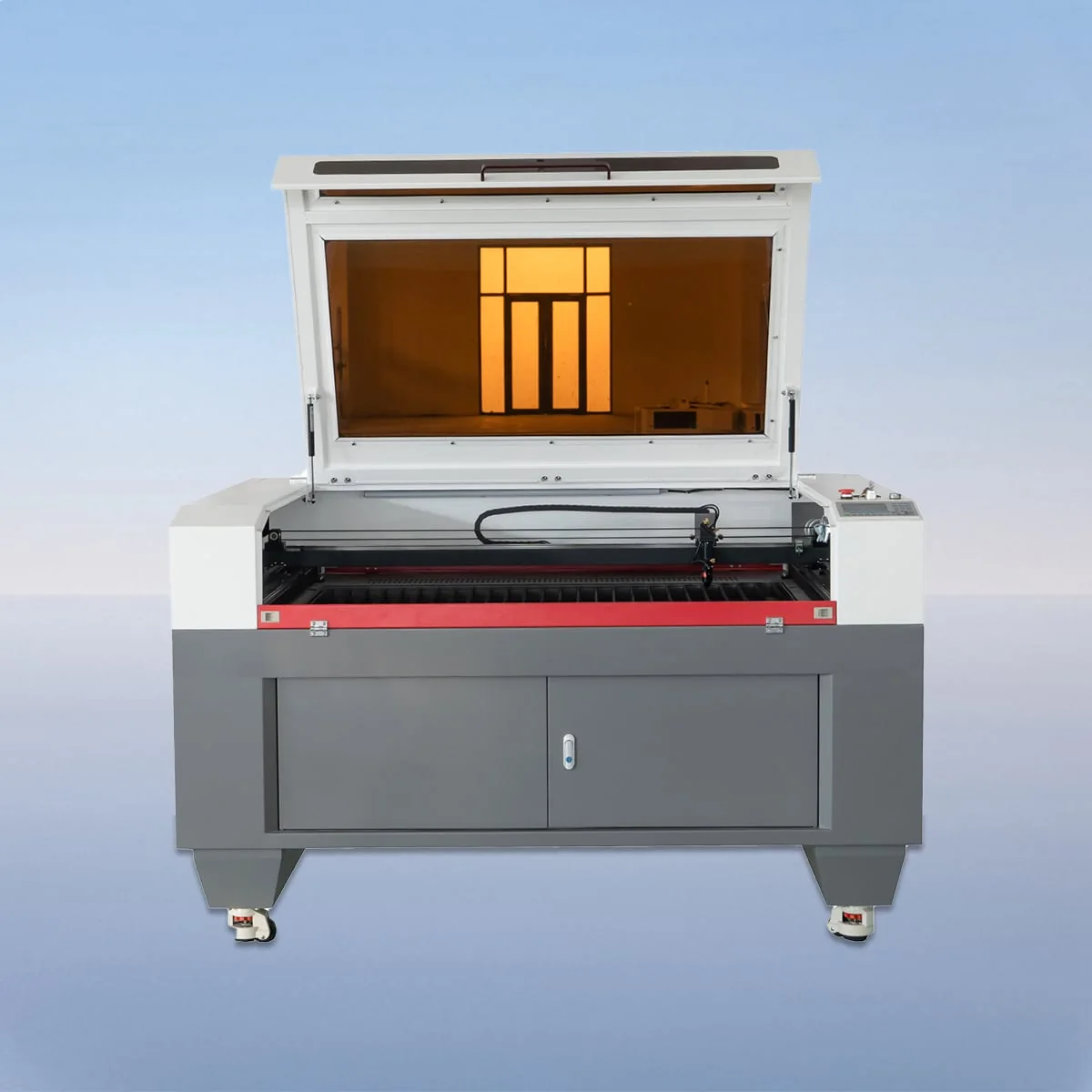
Laser Cutting Machine
VIC1325C is the 1300*2500mm working-area model in the VIC-C CO2 laser cutting series. The family describes a CCD camera for process monitoring, material alignment and positioning. Its published configuration also includes a CO2 head and tube, linear guides, stepper motors and belt drive.
Begin a quotation request with the full layout and the material that will support it. For this model, the table selection, file dimensions and physical positioning references should describe the same intended job. A drawing of an isolated component may leave important questions about the incoming blank and its presentation unanswered.
| Specification | VIC1325C |
|---|---|
| Working Area | 1300*2500mm |
| Laser Type | CO2 Laser |
| Working Table | Knife Table or Honeycomb Table |
| Laser Power | 80-600W |
| Power Supply | 220V/50HZ, 110V/60HZ |
| Min Line Width | ≤0.15mm |
| Position Accuracy | 0.01mm |
| Repetition Accuracy | 0.02mm |
| Cutting Speed | 150mm/s |
| Control System | Ruida (USB Interface) |
| Graphic Format Support | PLT, DXF, BMP, JPG, AI, etc |
Configuration options vary by model. Confirm the final specification, selected components and operating requirements with your quotation.
The VIC1325C working area lists 1300mm in one direction and 2500mm in the other. VIC1318C provides a same-family comparison at 1300*1800mm. If you are considering VIC1530C at 1500*3000mm instead, both listed dimensions change. Compare each complete rectangle with the layout rather than choosing by only its longer dimension.
The table alternatives are Knife Table or Honeycomb Table. Aluminum blades are described for the knife-table arrangement. Ask which support surface is proposed for the particular blank and explain any positioning supports you require. A list of two alternatives does not establish that both arrive with the same machine order.
The camera description provides a starting point for discussing how material will be aligned and monitored during cutting. Identify the references on the work and the intended relationship between them and the artwork. The CCD feature does not, by itself, specify automatic defect inspection, correction performance or the dimensional result of the completed part.
VIC-C is described as cutting and engraving equipment, with wood and acrylic named in the source. Provide the actual grade or material description and thickness. If the same layout is intended for several materials, separate the requirements and desired results; a single drawing does not make their application assessments interchangeable.
Suppose a purchasing team receives a component drawing and a separate production layout. Send both, state which revision governs and identify the edges used to position the material. Ask the proposed camera and table arrangement to be discussed against that full package. This keeps file preparation and physical setup connected without claiming a tested manufacturing outcome.
The controller entry is Ruida with a USB interface. Named file formats include PLT, DXF, BMP, JPG and AI. Provide artwork at its intended scale, with units and revision identified. Explain whether any accompanying picture is a location guide or an example of the desired appearance so its purpose remains clear.
An 80-600W power range is listed for the model. Request a specific proposed power and the electrical version in the quotation. The supply entries are 220V/50HZ and 110V/60HZ; these should be resolved against the destination supply instead of left as an assumption that one configuration suits both.
Min Line Width is listed as ≤0.15mm, Position Accuracy as 0.01mm and Repetition Accuracy as 0.02mm. Cutting Speed is stated at 150mm/s. Keep those fields distinct from the acceptance requirements for your material and layout. The technical discussion should identify how the proposed result is to be assessed, including any sample information needed.
1300*2500mm. The complete blank and proposed layout should be considered against both dimensions, while machine footprint is requested separately.
Knife and honeycomb are published choices, not a statement that both are supplied. Ask the quotation to identify the selected working surface.
Provide positioning references and the intended artwork relationship. The source describes monitoring, alignment and positioning rather than a guaranteed inspection or correction result.
VIC1318C lists 1300*1800mm and VIC1530C lists 1500*3000mm. Keep the dimensions and full model names together when comparing your layout.
Include the format, units, scale and drawing revision. Distinguish individual component drawings, the complete production layout and any reference images.
Share your material, dimensions and process. Start a conversation about the right configuration.