How does VIC1610C differ in area from VIC1318C?
Their listed areas are 1600*1000mm and 1300*1800mm. Compare both dimensions because neither rectangle is larger than the other in every direction.

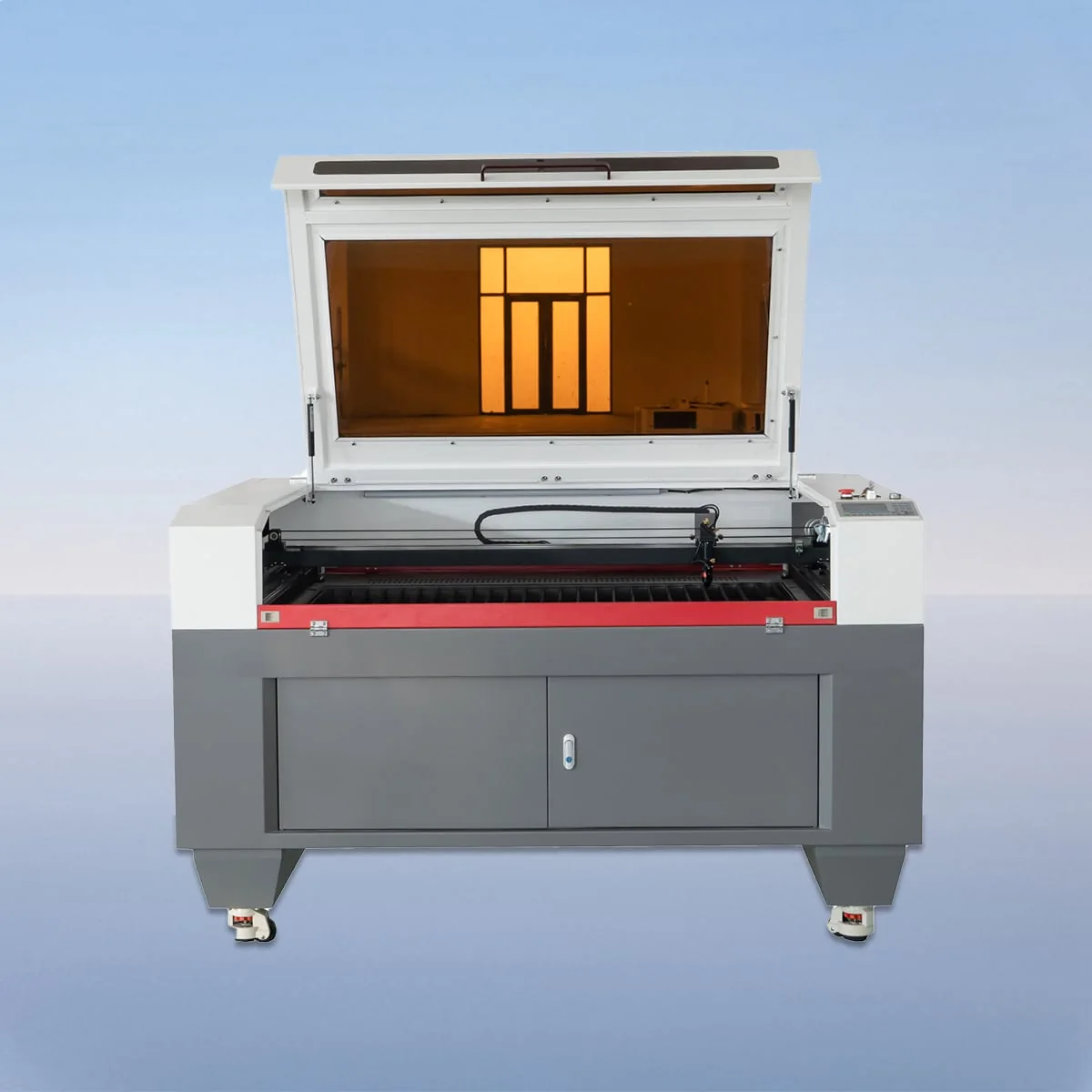
Laser Cutting Machine
VIC1610C has a 1600*1000mm working area in the VIC-C CO2 laser cutting range. Its series configuration includes a CCD camera for process monitoring, material alignment and positioning. The published table pairs this working-area entry with an 80-600W power range, Ruida USB control and knife or honeycomb table alternatives.
The shape of the working rectangle matters when comparing VIC1610C with VIC1318C, which lists 1300*1800mm. One listed dimension increases while the other decreases. Compare a complete workpiece layout with both rectangles rather than assuming the next model in a list is larger in every direction.
| Specification | VIC1610C |
|---|---|
| Working Area | 1600*1000mm |
| Laser Type | CO2 Laser |
| Working Table | Knife Table or Honeycomb Table |
| Laser Power | 80-600W |
| Power Supply | 220V/50HZ, 110V/60HZ |
| Min Line Width | ≤0.15mm |
| Position Accuracy | 0.01mm |
| Repetition Accuracy | 0.02mm |
| Cutting Speed | 150mm/s |
| Control System | Ruida (USB Interface) |
| Graphic Format Support | PLT, DXF, BMP, JPG, AI, etc |
Configuration options vary by model. Confirm the final specification, selected components and operating requirements with your quotation.
Mark the two dimensions of your proposed blank and identify its intended orientation. For the VIC1610C working area, keep those dimensions distinct from any finished component cut from the blank. If several components will share a layout, provide the full arrangement rather than only the drawing of the largest piece.
The CCD camera description concerns monitoring and alignment of the material during the cutting process. Explain the positioning references on the proposed blank and the result you want an operator to check. The source does not assign an automatic defect-detection capability or establish that the camera will correct every placement error.
The CO2 head and tube are described alongside linear guides, stepper motors and belt drive. The table offers knife or honeycomb support, while the configuration section describes aluminum blades for the knife arrangement. Have the proposed components and surface identified in the offer; table geometry alone is not a complete equipment specification.
VIC-C is described for cutting and engraving, with wood and acrylic as material examples. Specify the material type and thickness for each proposed job. Keep desired edge quality, engraved appearance and finished dimensions as requirements to assess, rather than results already established by the series' general material description.
Suppose the same component can be arranged in two orientations on a blank. Submit both layouts and explain which edges must remain the reference for positioning. Ask how the proposed camera arrangement would be used in each case. This creates a practical comparison between the different working rectangles without inventing a production yield or cycle time.
Ruida with a USB interface is the control-system entry. PLT, DXF, BMP, JPG and AI appear in the supported graphic formats. Attach a file with identified units and scale, plus its revision. If a separate illustration explains the layout orientation, label it so it cannot be confused with the file intended for processing.
The electrical entries are 220V/50HZ and 110V/60HZ. Confirm which version is proposed for your installation and which laser power is selected within the listed range. Neither the pair of supply values nor the power range should remain an unresolved shorthand in the final configuration schedule.
The specification states 0.01mm Position Accuracy, 0.02mm Repetition Accuracy and 150mm/s Cutting Speed. These fields do not define the time or finished tolerance of your layout. Include the required result and any proposed sample check in the enquiry, then request actual machine dimensions for the separate installation-space review.
Their listed areas are 1600*1000mm and 1300*1800mm. Compare both dimensions because neither rectangle is larger than the other in every direction.
No. The processing rectangle is a separate field. Obtain external machine dimensions and the required loading and access arrangement for installation planning.
The series describes process monitoring, material alignment and positioning. Submit the intended reference edges and discuss the operating method for your actual blank.
Knife or honeycomb are listed alternatives. The aluminum blade description concerns the knife table; the selected surface should be stated in the offer.
Send both layouts with dimensions, material details and positioning references. Identify the preferred orientation and the required finished result for each proposed arrangement.
Share your material, dimensions and process. Start a conversation about the right configuration.