What differs between VIC6040C and VIC9060C?
Their working-area entries are 600*400mm and 900*600mm. Both have the listed 80-600W power range, so power and area should be specified separately.

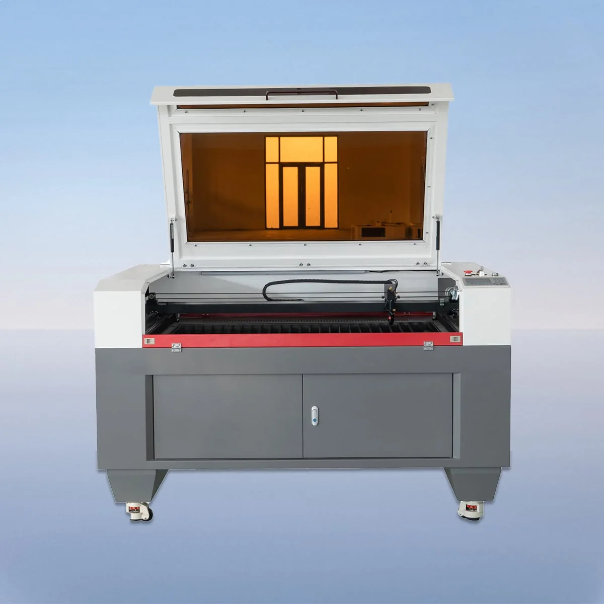
Laser Cutting Machine
VIC-C is a CO2 laser cutting machine series with a CCD camera for monitoring and alignment. The camera gives this family a specific role in a buying discussion: explain what must line up on the proposed workpiece, with the relevant positions marked on the design.
The equipment description includes a CO2 head and tube, linear guides, a stepper motor and belt drive. It names wood and acrylic for cutting and engraving. Seven working-area models provide the format choices, with an 80-600W power range listed across the family.
Choose an individual model below to view its complete technical specification. The series overview shows selected parameters for comparison.
VIC6040C provides 600*400mm, followed by VIC9060C at 900*600mm. VIC1390C is 1300*900mm and VIC1610C is 1600*1000mm. Match the entire workpiece outline to the area, including its orientation. A single longest dimension does not describe that layout.
VIC1318C and VIC1325C have the same 1300mm first dimension, paired with 1800mm and 2500mm. VIC1530C is the 1500*3000mm option. Those three entries are useful to compare where the second dimension of the working area is central to the proposed design.
The CCD function is monitoring and alignment assistance. Define the reference positions that matter and the intended operation around them. Automatic defect detection or correction is not established by that description, so those should not be assumed from the presence of a camera.
For VIC-C CO2 laser cutting machine planning, distinguish cut contours from engraving areas on the drawing. Mark the alignment references on the same version of that drawing, rather than leaving them in an unrelated photograph or verbal description. The intended task is easier to discuss when all three requirements can be seen together.
For wood or acrylic work, identify the exact material and thickness. If the design involves several operations, describe the sequence you want considered. The published material examples locate the product's intended use; the detailed drawing defines the particular work you are asking about.
Where one order contains several designs, keep a labeled file for each and state the quantities. Show which alignment requirement stays the same and which changes between designs. This gives the camera discussion concrete reference points without treating every job as an identical process.
The table specification offers Knife Table or Honeycomb Table, and the configuration description discusses an aluminum blade table. Identify the chosen surface alongside the proposed alignment task. It should be clear which worktable is being considered for the actual workpiece arrangement.
Ruida control with USB interface is listed. The graphic-format list includes PLT, DXF, BMP, JPG and AI. Supply the intended file type and the same reference positions used in the application notes. This connects the design information with the control configuration under discussion.
The published precision entries are 0.01mm position accuracy, 0.02mm repetition accuracy and minimum line width no greater than 0.15mm. Cutting speed is listed at 150mm/s. Preserve these distinctions when comparing the equipment with the finished-part requirements; a material-specific processing schedule is not provided here.
For the electrical configuration, state whether the site requires 220V/50HZ or 110V/60HZ, the two listed entries. The resulting equipment request can identify the area model, proposed power, worktable and supply, with a separate, clearly illustrated alignment requirement.
Their working-area entries are 600*400mm and 900*600mm. Both have the listed 80-600W power range, so power and area should be specified separately.
The source describes monitoring and alignment. It does not establish automatic inspection or correction of every defect, and the required alignment task should be defined in the inquiry.
Wood and acrylic are named for cutting and engraving. Exact material, thickness and finished-part requirements are still needed to describe the proposed job.
VIC1530C has a 1500*3000mm working area. VIC1325C is the separate 1300*2500mm option; neither entry is the outside machine footprint.
Provide the design with reference positions marked, distinguish the operations and identify the material and thickness. For several designs, label what stays the same and what changes.
Share your material, dimensions and process. Start a conversation about the right configuration.