What working area is published for VIC1530C?
1500*3000mm. These are processing-area dimensions; obtain external machine dimensions and access requirements separately when preparing an installation plan.

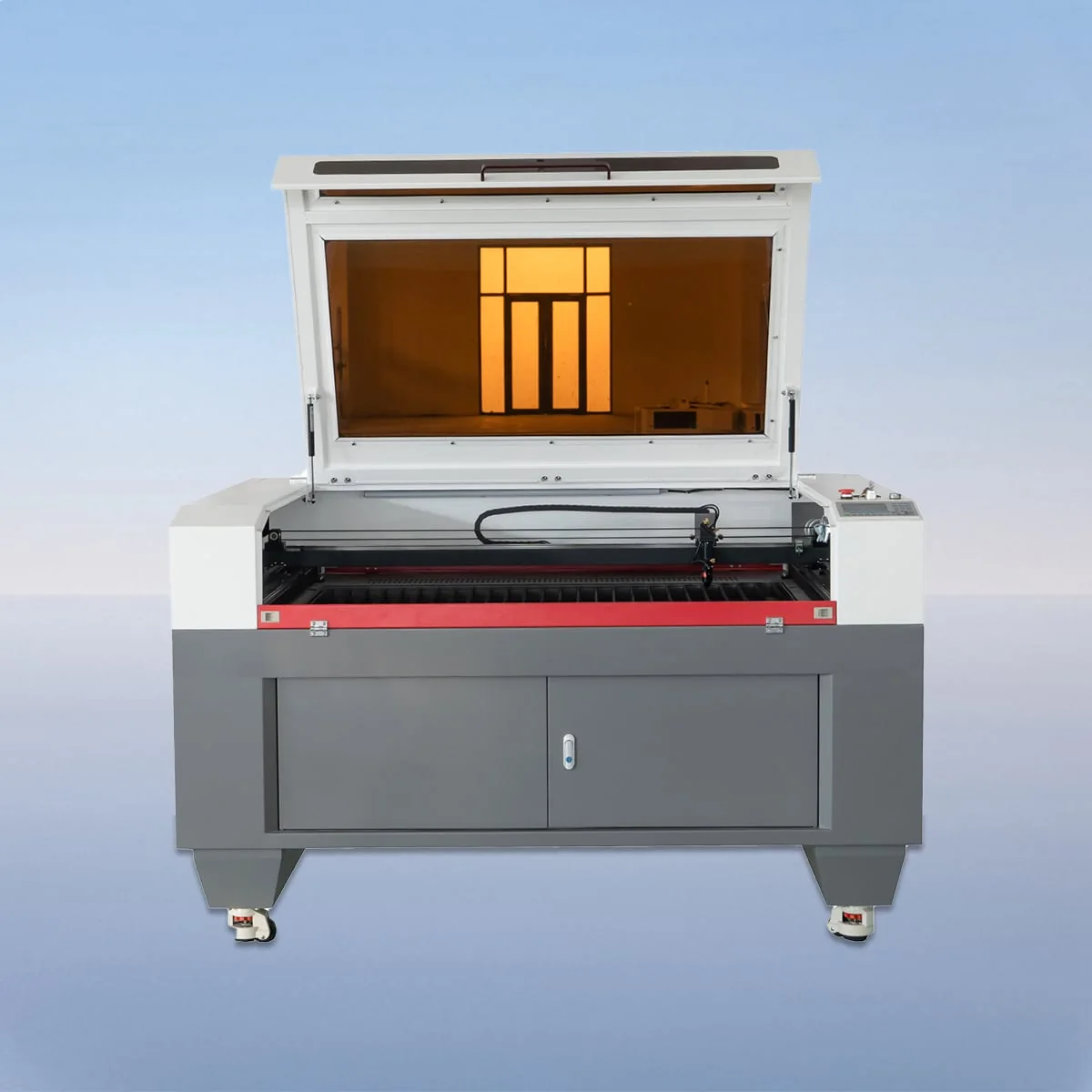
Laser Cutting Machine
VIC1530C has a published 1500*3000mm working area in the VIC-C CO2 laser cutting range. The series describes a CCD camera for cutting-process monitoring, material alignment and positioning. It lists knife or honeycomb table alternatives, an 80-600W laser power range and Ruida control with a USB interface.
A working-area choice and an installation-space decision answer different questions. Use the 1500*3000mm rectangle to discuss the material and proposed layout. Request actual equipment dimensions for the workshop plan, together with the access and handling arrangement intended for the offered configuration. The working area alone cannot complete that plan.
| Specification | VIC1530C |
|---|---|
| Working Area | 1500*3000mm |
| Laser Type | CO2 Laser |
| Working Table | Knife Table or Honeycomb Table |
| Laser Power | 80-600W |
| Power Supply | 220V/50HZ, 110V/60HZ |
| Min Line Width | ≤0.15mm |
| Position Accuracy | 0.01mm |
| Repetition Accuracy | 0.02mm |
| Cutting Speed | 150mm/s |
| Control System | Ruida (USB Interface) |
| Graphic Format Support | PLT, DXF, BMP, JPG, AI, etc |
Configuration options vary by model. Confirm the final specification, selected components and operating requirements with your quotation.
VIC1530C has a working area of 1500*3000mm in the published VIC-C model table. VIC1325C, for comparison, lists 1300*2500mm. Keep both dimensions with the incoming blank and finished layout when discussing model selection. A larger rectangle does not establish a particular output increase, material utilization or production cycle.
The camera is described for monitoring the cutting process and supporting material alignment and positioning. Show the location references on the complete workpiece, not just an enlarged detail of one feature. Discuss the proposed operating method without assuming automatic defect detection, automatic correction or a specified print-registration accuracy from the CCD designation.
The configuration includes a CO2 cutting head and tube, linear guides, stepper motors and belt drive. An aluminum blade worktable is described, with knife or honeycomb alternatives in the table. Have the proposed support surface and component selection recorded alongside the model so the discussion refers to an identifiable machine configuration.
The VIC-C source describes cutting and engraving and names wood and acrylic. Identify the material specification, thickness and intended finished result for your project. If a large layout includes both an outer profile and engraved details, show which drawing information defines each requirement and which areas will be used for assessment.
Imagine planning a workstation for a full layout that also needs space for incoming material and completed parts. Provide the proposed floor plan and explain the handling sequence you want considered. Keep those installation questions separate from whether the artwork fits the published working area; both must refer to the same proposed equipment and job.
Supported graphic formats include PLT, DXF, BMP, JPG and AI. For the Ruida USB control discussion, supply the production file with its units, scale and revision. If you send a reduced-size preview, label it as a preview and keep the intended dimensions explicit so it does not replace the actual layout definition.
Ask for the selected laser power within the listed 80-600W range. The electrical table gives 220V/50HZ and 110V/60HZ; identify the destination supply and have the offered version specified. Machine dimensions, requested accessories and any separate installation responsibilities should be resolved in the same proposal rather than inferred from a catalogue entry.
The table lists 150mm/s Cutting Speed, 0.01mm Position Accuracy and 0.02mm Repetition Accuracy. These are published parameter fields, not a cycle-time or finished-tolerance commitment for the full working rectangle. State the required result and ask what application assessment is needed before relying on a proposed process for your layout.
1500*3000mm. These are processing-area dimensions; obtain external machine dimensions and access requirements separately when preparing an installation plan.
VIC1325C lists 1300*2500mm. Both listed dimensions are smaller, so compare the complete layout and incoming material with each model.
The family description covers process monitoring, material alignment and positioning. It does not establish an automatic inspection rate or a guaranteed outcome across a full layout.
Use actual equipment dimensions for that purpose and identify the proposed loading and access arrangement. The working rectangle alone is insufficient to plan the installation.
Send the material specification and thickness, the complete drawing with units and revision, positioning references and finished requirements. Add installation and handling information as a separate part of the brief.
Share your material, dimensions and process. Start a conversation about the right configuration.